MCP23017, a powerful I/O expander integrated circuit that opens up new possibilities for microcontrollers. This guide provides detailed insights into understanding the MCP23017, its uses, setup process, and connections with popular development platforms like Arduino and Raspberry Pi.
What is MCP23017 explained?
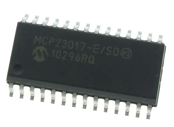
The MCP23017 is a popular I/O expander integrated circuit (IC) developed by Microchip Technology. It provides additional input/output (I/O) pins to microcontrollers, allowing them to expand their capabilities in terms of controlling various external devices.
What is the use of MCP23017?
The primary use of the MCP23017 is to increase the number of available I/O pins for microcontrollers. This is particularly useful when a microcontroller has limited I/O pins but needs to interface with multiple sensors, switches, or other peripherals. By using the MCP23017, developers can significantly expand the number of devices they can connect to their microcontroller.
MCP23017 EACD Model
PCB symbol and Footprint


Datasheet
You can click the pictures below to learn more about MCP23017!

How to set up MCP23017?
To set up the MCP23017, you will need to follow a few steps.
- First, you need to determine the address of the MCP23017 IC, as it can have multiple addresses depending on the configuration of its A0, A1, and A2 pins.
- Once you know the address, you can connect the necessary power and ground pins. You also need to connect the SDA and SCL pins to the corresponding pins on your microcontroller.
- Finally, you can configure the MCP23017 through software by sending commands over the I2C bus.
How to connect MCP23017 to Arduino?
Connecting the MCP23017 to an Arduino involves a straightforward process.
- Start by connecting the VCC and GND pins of the MCP23017 to the 5V and GND pins of the Arduino, respectively.
- Connect the SDA and SCL pins of the MCP23017 to the corresponding pins on the Arduino (usually A4 and A5).
- Additionally, set the address of the MCP23017 by connecting its A0, A1, and A2 pins to either GND or VCC.
- Finally, upload the appropriate code to your Arduino, which will allow you to control the MCP23017.
How to connect MCP23017 to Raspberry Pi?
Connecting the MCP23017 to a Raspberry Pi also requires a few steps.
- Begin by connecting the VCC and GND pins of the MCP23017 to the 3.3V and GND pins of the Raspberry Pi, respectively.
- Connect the SDA and SCL pins of the MCP23017 to the corresponding pins on the Raspberry Pi (usually GPIO2 and GPIO3).
- Similarly, set the address of the MCP23017 using its A0, A1, and A2 pins connected to either GND or 3.3V.
- Finally, you can control the MCP23017 through software by using the appropriate libraries and code on your Raspberry Pi.
Comparison About MCP23017
MCP23017 vs MCP23016
The MCP23016 is another I/O expander from Microchip, possessing similarities with the MCP23017. The primary difference between these two ICs lies in the number of available I/O pins. While the MCP23017 offers 16 I/O pins, the MCP23016 has only 16 pins in total, limiting it to 8 I/O pins. Therefore, if your project requires more I/O pins, the MCP23017 would be the preferred choice.
MCP23017 vs MCP23018
The MCP23018 is also an I/O expander IC from Microchip, closely related to the MCP23017. The main distinction here is the inclusion of interrupt functionality in the MCP23018, which allows it to generate interrupts to the microcontroller when certain events occur on its I/O pins.
If you require interrupt capabilities for your project, the MCP23018 would be the suitable option. However, if interrupts are not necessary, the MCP23017 can still perform effectively.
MCP23017 vs PCF8575
The PCF8575, manufactured by NXP Semiconductors, is another I/O expander that shares some similarities with the MCP23017. Both ICs offer 16 additional I/O pins, but there are slight differences in their features.
One notable distinction is their communication interface: the MCP23017 uses the I2C protocol, while the PCF8575 communicates via the I2C-bus. Additionally, the PCF8575 operates at a higher voltage range than the MCP23017. Consider the specific requirements of your project to determine which IC suits your needs better.
MCP23017 vs MCP23S17
The MCP23S17 is a variant of the MCP23017 that communicates using the Serial Peripheral Interface (SPI) bus, whereas the MCP23017 uses I2C. The choice between these two depends on the communication interface already implemented or preferred in your system. If you are already using I2C, the MCP23017 would be more compatible. Alternatively, if SPI is already established or desired, the MCP23S17 would be the appropriate selection.
MCP23017 vs 74HC595
While the 74HC595 is not an I/O expander like the MCP23017, it is worth comparing since it serves a similar purpose of expanding digital output pins. The primary difference is that the 74HC595 is a shift register IC, providing serial-in parallel-out functionality for driving multiple outputs.
In contrast, the MCP23017 offers both input and output pins, making it suitable for bidirectional applications. Consider whether you require only output expansion (74HC595) or both input and output expansion (MCP23017).
FAQs
What is the source current of the MCP23017?
The source current (I_source) for the MCP23017 varies depending on the specific operating conditions and configurations. Generally, each I/O pin can sink or source up to 25 mA individually. It is recommended to refer to the datasheet for detailed information regarding source current limits and overall device specifications.
What is the output voltage of MCP23017?
The MCP23017 operates with a supply voltage range typically between 1.8V and 5.5V. The logic high-level output voltage (V_oh) is rated at a minimum of 2.4V when sourcing up to 6 mA of current, ensuring compatibility with various microcontrollers and digital devices.
What is the frequency of MCP23017 I2C?
The MCP23017 supports I2C communication, which operates at various standard frequencies. The typical I2C clock frequency used with the MCP23017 ranges from 100 kHz to 400 kHz. However, it is important to note that the specific clock frequency in your application depends on the capabilities and requirements of your microcontroller or I2C master device.
What is the default address of the MCP23017?
The MCP23017 has a configurable I2C address, allowing multiple devices to be connected on the same bus. The default address of the MCP23017 is 0x20 but can be changed by configuring its address pins (A0, A1, and A2) to different logic levels. This flexibility enables you to connect up to eight MCP23017 devices on a single I2C bus, each with a unique address.

Conclusion
By harnessing the power of the MCP23017, developers can extend their microcontroller’s capabilities, adding more I/O pins to accommodate a wide range of external devices. With this comprehensive guide at your disposal, you are now equipped to explore the vast potential of the MCP23017 and unleash the full potential of your microcontroller projects.