The MCP2515 CAN Controller is a widely used and highly regarded component in the field of Controller Area Network (CAN) communication. This compact and versatile device plays a crucial role in enabling reliable and efficient communication between various applications. In this blog, we will explore the MCP2515 CAN Controller, providing you with a comprehensive guide to understanding and utilizing this essential component.
What is MCP2515?
The MCP2515 is an integrated circuit (IC) that serves as a controller for the Controller Area Network (CAN) bus. It provides communication capabilities between microcontrollers or other devices using the CAN protocol. The MCP2515 handles tasks such as message filtering, transmitting, receiving, and error detection on the CAN bus.
How does MCP2515 work?
The MCP2515 works by interfacing with a microcontroller through a serial peripheral interface (SPI). It communicates with the microcontroller to exchange data and control signals. The MCP2515 contains various registers that can be accessed and configured by the microcontroller to set up filters, masks, and other settings for message filtering and handling.
When a message needs to be transmitted, the microcontroller sends the message data and relevant control information to the MCP2515. The MCP2515 then takes care of encoding the data into a CAN frame, adding the necessary control bits, and transmitting it onto the CAN bus.
On the receiving side, the MCP2515 continuously monitors the CAN bus for incoming messages. When a valid message is detected, it stores the received data in its internal buffers and notifies the microcontroller through an interrupt or other means. The microcontroller can then read the received message from the MCP2515’s buffers and process it accordingly.
Features
- Supports CAN 2.0B protocol specification.
- Operates at a supply voltage range of 2.7V to 5.5V.
- Offers SPI interface for communication with a microcontroller.
- Provides message acceptance filters and masks for efficient message filtering.
- Supports both standard (11-bit) and extended (29-bit) identifier formats.
- Contains transmit and receive buffers for storing messages.
- Includes error detection and reporting mechanisms.
- Offers programmable bit rates ranging from 10 kbps to 1 Mbps.
- Provides an interrupt pin for notifying the microcontroller of events.
- Has low power consumption, making it suitable for battery-powered applications.
- Offers various operating modes to suit different application requirements.
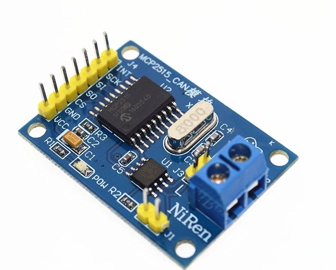
MCP2515 Module Pinout

MCP2515 ECAD Model
PCB symbol and Footprint


Datasheet
If you want to know more useful information about MCP2515, you can click here right now!
Practical Applications
The MCP2515 is widely used in various applications that require reliable and efficient communication over the CAN bus. Some common applications include:
- Automotive: The MCP2515 is commonly used in automotive systems for communication between different electronic control units (ECUs), such as engine control modules, transmission control modules, and body control modules. It enables seamless data exchange and coordination between these systems.
- Industrial Automation: The MCP2515 finds applications in industrial automation systems, where it enables communication between different devices, sensors, and actuators. It allows for real-time control and monitoring of processes in industries such as manufacturing, robotics, and logistics.
- Home Automation: The MCP2515 can be utilized in home automation systems to facilitate communication between smart devices, enabling centralized control and monitoring of various functions like lighting, security systems, and energy management.
- Medical Devices: The MCP2515 is also employed in medical devices and equipment for communication between different modules, ensuring seamless data transfer and integration for accurate diagnostics and treatment.
- IoT Applications: The MCP2515 plays a crucial role in Internet of Things (IoT) applications, where it enables communication between IoT nodes and gateways, facilitating data exchange and remote control functionalities.
How to set the baud rate in MCP2515?
Setting the baud rate in the MCP2515 involves configuring specific registers within the IC. The baud rate determines the speed at which data is transmitted and received on the CAN bus. To set the baud rate, the following steps are typically followed:
- Determine the desired baud rate for your application.
- Calculate the appropriate values for the timing registers based on the desired baud rate. The calculation involves considering factors such as oscillator frequency, desired bit time, and propagation delay.
- Write the calculated register values to the respective registers in the MCP2515 using the SPI interface. These registers include the CNF1, CNF2, and CNF3 registers, which control various timing parameters for the CAN bus.
- Configure other necessary settings, such as filtering options, interrupts, and operating modes, based on your application requirements.
- Enable the MCP2515 by setting the appropriate control bits in the configuration registers.
- Initiate communication with the microcontroller over the SPI interface to exchange data and control signals.
It is important to consult the MCP2515 datasheet and refer to the specific instructions provided by the manufacturer for accurate configuration and setup of the baud rate and other settings.

FAQs
What is the difference between MCP2510 and MCP2515?
The main difference between MCP2510 and MCP2515 is their technology and features. The MCP2510 is an older version of the CAN controller, while the MCP2515 is a newer and more advanced version. The MCP2515 offers additional features and improvements over the MCP2510, such as higher transmission speed and better compatibility with various microcontrollers.
What is the function of MCP2515?
The function of the MCP2515 is to act as a controller for the Controller Area Network (CAN) bus. It provides communication capabilities between microcontrollers or other devices through the CAN protocol. The MCP2515 handles tasks such as message filtering, transmitting, receiving, and error detection on the CAN bus.
What is the maximum voltage for MCP2515?
The maximum voltage for the MCP2515 is 5.5V. It operates on a supply voltage range of 2.7V to 5.5V. It is important to ensure that the voltage supplied to the MCP2515 does not exceed this limit to prevent damage to the IC.
What is the speed of the MCP2515 bus?
The speed of the MCP2515 bus depends on the specific configuration and settings. It supports data rates ranging from 10 kbps to 1 Mbps. The actual speed achieved will depend on factors such as the baud rate set, the length of the bus, and the number of connected nodes.
What is the maximum distance of MCP2515?
The maximum distance of the MCP2515 depends on the physical layer implementation of the CAN bus. In general, the maximum distance can reach up to several kilometers when using appropriate transceivers and wiring. However, it is important to note that signal integrity and noise immunity can be affected by longer distances, so proper considerations should be made in the design and installation of the CAN bus.
Conclusion
MCP2515 CAN Controller is a powerful and indispensable tool for facilitating seamless and efficient communication in CAN networks. Its robust features, ease of integration, and cost-effectiveness make it a preferred choice for numerous applications in automotive, industrial, and other domains. By harnessing the capabilities of the MCP2515, engineers and developers can unlock new possibilities and enhance the performance of their systems.