TIP35C is a power transistor that has gained a reputation for being both versatile and reliable among electronic enthusiasts and professionals alike. In this post, we will highlight its circuit, datasheet, pinout and discuss its equivalents or replacements. Whether you are a hobbyist or a professional electronic engineer, the TIP35C is sure to meet your requirements and exceed your expectations.
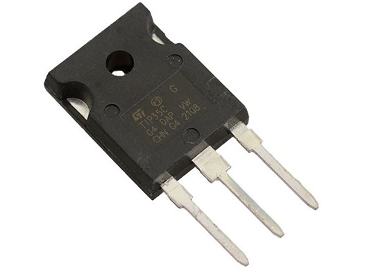
TIP35C by STMicroelectronics

As the manufacturer of the TIP35C, STMicroelectronics brings its expertise and commitment to delivering reliable and efficient products.
When it comes to reputation and reliability, the TIP35C transistor from STMicroelectronics has gained recognition for its consistent performance and durability. Designed to handle higher power levels and current loads, the TIP35C is well-suited for demanding applications where robustness is crucial. Its ability to withstand high temperatures and electrical stress makes it a reliable choice for various circuit designs.
In addition to the TIP35C, STMicroelectronics offers a range of other notable transistors that cater to different requirements and specifications. These include complementary transistors, such as the TIP36C, which work in conjunction with the TIP35C for applications requiring both NPN and PNP transistors.
TIP35C Circuit
The TIP35C transistor features a versatile circuitry that allows it to function effectively within electronic circuits. It is a bipolar junction transistor (BJT) with an NPN configuration. The transistor consists of three layers: the emitter, base, and collector. This arrangement enables the TIP35C to control the flow of current between the collector and emitter based on the current at the base terminal.
How the TIP35C functions within an electronic circuit?
Within an electronic circuit, the TIP35C serves as a switching or amplification component. As a switch, it can control the flow of current through a load by turning the transistor on or off. When used as an amplifier, the TIP35C can amplify weak electrical signals to higher power levels, allowing for faithful reproduction and amplification of audio or other signals.
Advantages and disadvantages of using TIP35C in a circuit
The TIP35C transistor offers several advantages in circuit design. Its high current and power handling capabilities make it suitable for applications that require robust performance, such as audio amplifiers or motor control circuits. Additionally, the TIP35C exhibits low saturation voltage, minimizing power losses and ensuring efficient operation.
However, it is important to note that the TIP35C may require adequate heat dissipation due to its power handling capability, which should be taken into consideration during circuit design.
Exploring the TIP35C Transistor Datasheet
The TIP35C transistor datasheet provides a comprehensive overview of the key specifications and electrical characteristics of the transistor.
The datasheet typically includes information on the operating conditions, maximum ratings, and electrical characteristics of the TIP35C transistor. Operating conditions may include recommended biasing conditions, such as voltage and current levels, while maximum ratings provide the upper limits for parameters such as current, power, and temperature that the transistor can handle without damage to the device.
Interpreting electrical characteristics, ratings, and limitations of the TIP35C transistor
- The electrical characteristics of the TIP35C transistor include parameters such as DC current gain, collector-emitter saturation voltage, and base-emitter voltage drop.
- The maximum voltage and current ratings must not be exceeded to avoid possible damage to the transistor or the entire circuit.
- The electrical characteristics of the TIP35C transistor must also be taken into account during circuit design, as they determine how the transistor will perform under various operating conditions.
Understanding the TIP35C Transistor Pinout
The TIP35C transistor pinout refers to the physical layout and function of each pin on the transistor.
The TIP35C transistor has three pins: the emitter, base, and collector. The emitter is typically connected to the negative side of the power supply or load, while the collector is connected to the positive side. The base pin is used to control the flow of current between the collector and emitter and is typically connected to a signal source or drive circuit.
To ensure proper connection and utilization, it is important to refer to the TIP35C pinout diagram provided in the datasheet. The pinout diagram indicates the location and function of each pin on the transistor, as well as any markings or identifiers that may be present on the physical package of the transistor. It is also significant to note any pin orientation or polarity requirements specified in the datasheet.
TIP35C Equivalent Transistors
If the TIP35C transistor is not readily available or suitable for a particular application, there are alternative transistors that can be used as replacements. It is essential to consider the specifications, pinouts, and performance of these equivalent transistors to ensure compatibility and proper functioning within the circuit.
Some alternative transistors that can be considered as replacements for the TIP35C include the MJ15003, 2N3055, and BDW93C. These transistors have similar electrical characteristics and power handling capabilities, making them potential substitutes for the TIP35C in various applications. However, it is essential to consult the datasheets and compare the specifications of these alternative transistors to ensure they meet the specific requirements of the circuit.
Comparing specifications, pinouts, and performance of TIP35C equivalents
When comparing the specifications of the TIP35C equivalents, it is crucial to consider parameters such as maximum voltage ratings, collector current ratings, and power dissipation capabilities. Additionally, the gain (hFE) and switching characteristics should be examined to determine if they align with the intended application. Pin compatibility and pinout diagrams should also be evaluated to ensure proper connection and utilization within the circuit.
TIP35C Replacing

When replacing a TIP35C transistor with an alternative, several factors need to be considered to ensure a safe and successful replacement. These factors include electrical compatibility, thermal considerations, and physical fit within the existing circuit.
Firstly, it is crucial to select an alternative transistor that has similar or better electrical characteristics compared to the TIP35C. The replacement transistor should have comparable voltage and current ratings, gain characteristics, and power handling capabilities to ensure compatibility with the circuit’s requirements.
Thermal considerations must also be taken into account when replacing the TIP35C. The substitute transistor should have similar thermal characteristics or higher power dissipation capabilities to handle the heat generated during operation. Proper heat sink selection and implementation may be necessary to ensure the replacement transistor operates within safe temperature limits.
Steps to safely replace TIP35C with an alternative transistor
To replace the TIP35C with an alternative transistor safely, it is advised to follow these steps:
- Consult the datasheets of both the TIP35C and the selected replacement transistor to compare their specifications and pinouts.
- Ensure that the pin configuration of the replacement transistor matches that of the TIP35C to facilitate a smooth substitution.
- Analyze the electrical characteristics of the replacement transistor and verify that it meets or exceeds the requirements of the circuit.
- Make any necessary modifications to the circuit layout, such as adjusting biasing resistors or driver circuits, to accommodate the new transistor if required.
- Take proper precautions during the physical replacement process, such as avoiding electrostatic discharge and confirming correct placement and orientation of the replacement transistor.
- Conduct thorough testing and analysis after replacing the TIP35C with the alternative transistor to ensure proper functionality and performance.
By carefully considering these factors and following the outlined steps, the replacement of the TIP35C with an alternative transistor can be carried out safely and effectively, allowing for continued operation of the circuit.
Conclusion
TIP35C transistor has undoubtedly proven its worth as a versatile and reliable component in the field of electronics. Its exceptional performance, robust design, and wide range of applications have made it an indispensable tool for countless projects. Whether you are building amplifiers, power supplies, or motor control systems, the TIP35C is a go-to choice for its ability to handle high currents and voltage requirements.